Let's Build a Simple Raspberry-pi Surveillance System
Let’s build a security monitoring system that will watch over your house, business, garage, or any other property while you’re away. If someone enters your property without permission, it will sound an alarm, capture photos and videos of the intruders, and email them to you.
List of Components
The modules that we are going to be using are:
- Infared sensor
- Raspberry-pi camera module
- Raspberry-pi 3
Infared Sensor
First, let’s understand what Infrared Radiation (IR)? Infrared is a region of the electromagnetic radiation spectrum, where the wavelength is be- tween 700 nm to 1 mm, which is more than the wavelength of visible light and less than radio waves. The frequency of IR is in the range of 300 GHz to 400 GHz, which is higher than the frequency of microwaves, but lower than that of visible light.
IR waves are not visible to human eye unlike visible light, but can be fo- cused, reflected, and polarized just like visible light.
IR is mostly used in wireless communication, remote controls, sensors, thermal imaging, and night vision devices, but we will focus only on IR sensors in this chapter.
IR sensors are the devices that emit or/and detect IR radiation. The work- ing principle of any IR sensor is governed by Plank’s radiation law. As per Plank’s radiation law, any object that has a temperature not equal to abso- lute zero (which is zero kelvin (0° K)) emits radiation.
In our case, we use IR sensors for obstacle or object detection, and for these applications the IR sensor module should consist of the following components:
- IR transmitter: An IR transmitter is a source of IR radiation for which IR LEDs and lasers are used.
- Transmission medium: For the transmission of IR waves, a medium such as a vacuum, atmosphere, or optical fibers is required.
- Optical component: Materials such as quartz are used to focus the in- frared radiation in a particular area. Optical lenses such as quartz, germanium, and silicon are used to make optical components.
- IR receiver/detector: Photodiodes and LED are used as IR receivers and detectors respectively, which have good photo sensitivity for in- frared radiations.
- A signal processing module: A signal processing module is used to amplify the signal received by the IR detector because the amplitude of the signal is very small.
Passive Infared sensors (PIR)
Passive Infrared Sensors (PIR sensors) do not need an infrared source to operate. PIR sensors detect the infrared rays emitted. The main applica- tion of these motion detection sensors is to the check the presence of any human or animal since the body of a human and animal radiates infrared energy.
Let’s understand the anatomy of the PIR sensor module that we will be using to build our surveillance system. We use the readily available HC- SR501 PIR Sensor module. Refer to the figure below:
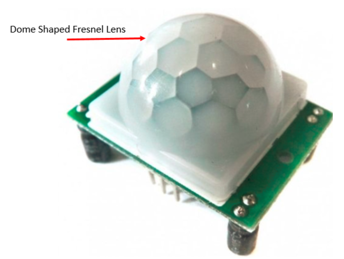
The preceding picture shows the top view of the PIR module with a dome-shaped fresnel lens mounted on it. This lens helps to focus infrared radiation.
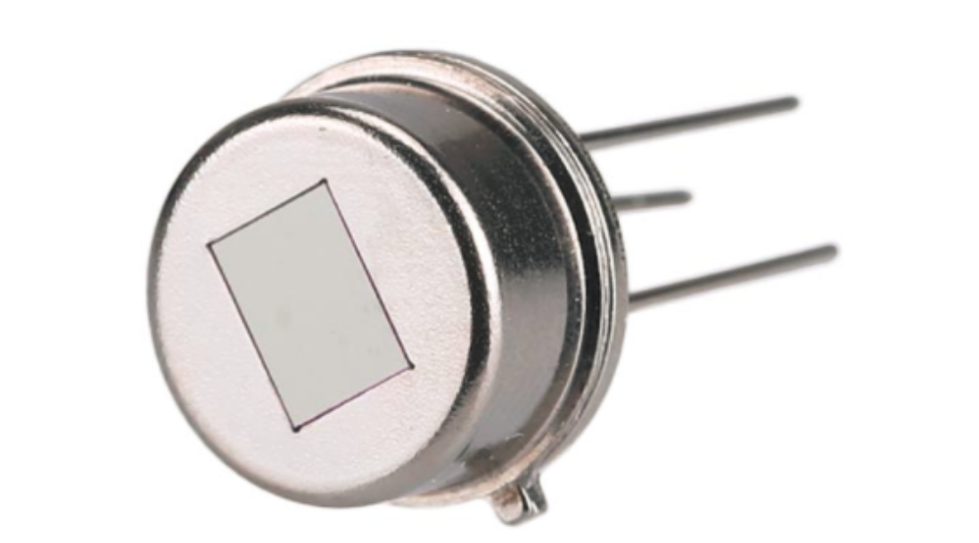
Inside this fresnel lens, there is a pyroelectric sensor, which detects the IR radiation, which shows a picture of the pyroelectric sensor enclosed in a metal body with a rectangular crystal in the center:
Along with the pyroelectric sensor, supporting circuitry is situated on the other side of the module,
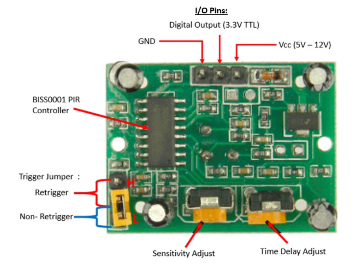
The supporting circuitry has a few important components that play a major role in the operation of the PIR sensor module:
- I/O pins:
- The first pin is for powering the sensor itself, marked as Vcc. The PIR sensor has an operating range of 5V to 12V.
- The second pin reads the output of the PIR sensor, marked as 3.3V TTL. It generates a digital output, which goes high when the sensor detects infrared radiation and goes low when there is no radiation in its range.
- The third pin is for grounding the sensor module marked as GND.
- B1SS0001 PIR controller IC:
- A CMOS-based chip designed specifically for human-infrared sensor control circuits
- Low power consumption and suitable for battery-powered operations
- High input impedance operational amplifier
- Bi-directional level detector/excellent noise immunity Built-in power up disable and output pulse control logic
- Dual operating modes: retriggerable and nonretriggerable
-
Trigger settings include three pins and at any time only two pins are shorted using the jumper. When the pin marked H is shorted with the middle pin, the sensor works in retrigger mode. In retrigger mode, the PIR sensor gives continuous high output for a cer- tain duration of time when it detects any human body (infrared radiation is emitted from the human body due to body heat). And when the pin marked as L (refer to Figure 6.3) is shorted with the middle pin, the sensor works in nonretrigger mode. In nonretrigger mode, the PIR sensor’s output keeps on switching between high and low when it detects any human body.
-
Sensitivity of the PIR sensor can be altered using the Trimpot pro- vided on the module and marked as Sensitivity Adjust. When the Trimpot is turned in a clockwise direction, the sensitivity is increased and it detects even the slightest movement of a human body (a source of infrared radiation) from a distance of 6 meters or more approximately. And when it is turned in an anticlockwise direction, the sensitivity is decreased and it detects motion within a small range of 2 to 3 meters.
- Delay time determines how long the PIR sensor’s output will remain high after detecting the motion. A Trimpot marked as time delay Adjust is provided to vary the delay time. The time value can be set from a few seconds to few minutes. When the Trimpot is turned in a clockwise direction, the delay time increases and the output will re- main high for a longer period; when it’s turned anticlockwise, the delay time reduces.
Until now, we have discussed the anatomy of the PIR sensor module. Let’s understand how the PIR sensor actually works. A PIR sensor has two slots and each slot detects infrared radiation separately. Here, each slot is made up of IR-sensitive material:
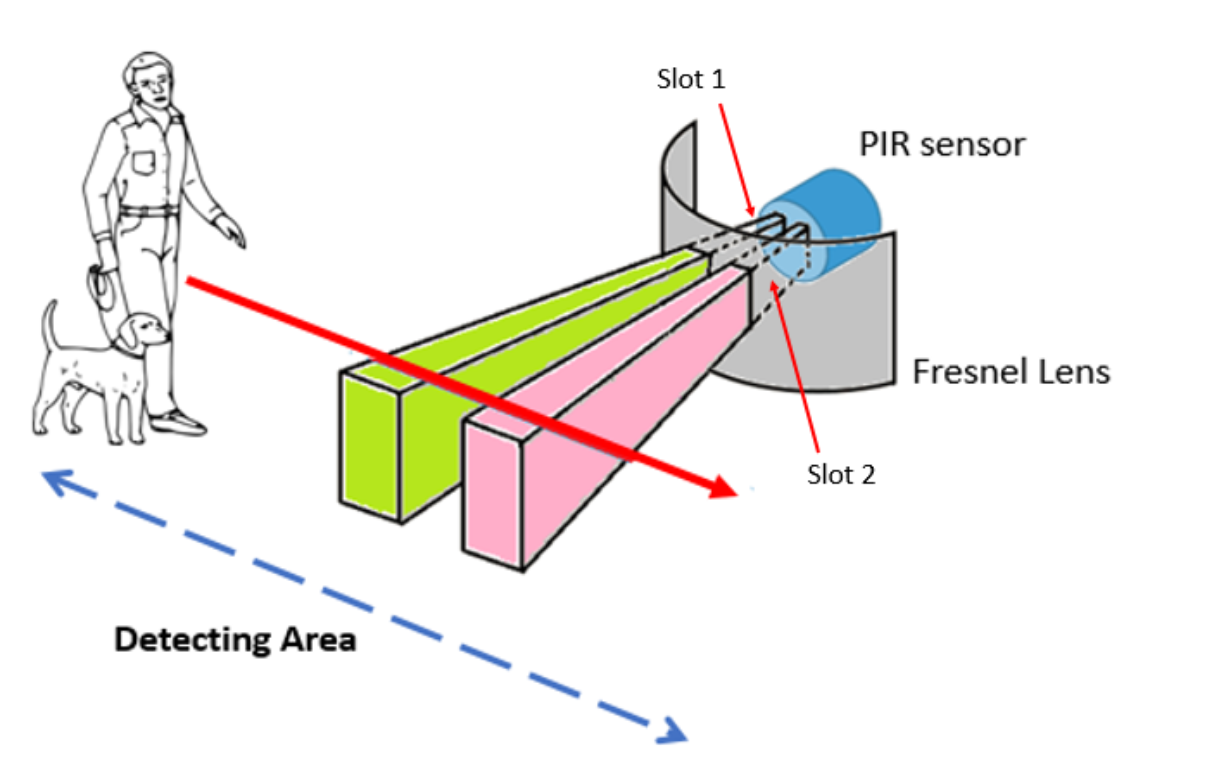
When there is no movement in front of the sensor, it remains in the idle state and both Slot 1 and Slot 2 detect the same amount of infrared radia- tion. When a warm body like that of a human or an animal passes by the detecting area, the IR radiation from the body is first detected by Slot 1 of the PIR sensor, which results in a positive differential change between two slots. And when the body leaves the detecting area, the IR radiation is detected by Slot 2, which results in a negative differential change be- tween the two slots. The combination of this positive and negative differ- ential change results in the output signal at the PIR sensor, which is being read out through I/O pins.
Raspberry-Pi Camera Module
Any security surveillance system is incomplete without the digital eyes of a camera. With the use of a camera, we can keep a real-time watch at our place or premises even when we are not present. If any trespasser enters our premises, then with a combination of sensors and camera, we can make a video recording or take pictures, which can help to track down the trespasser later on.
In our use case, we will use the Raspberry Pi camera module, which is an add-on accessory provided by the Raspberry Pi foundation itself.
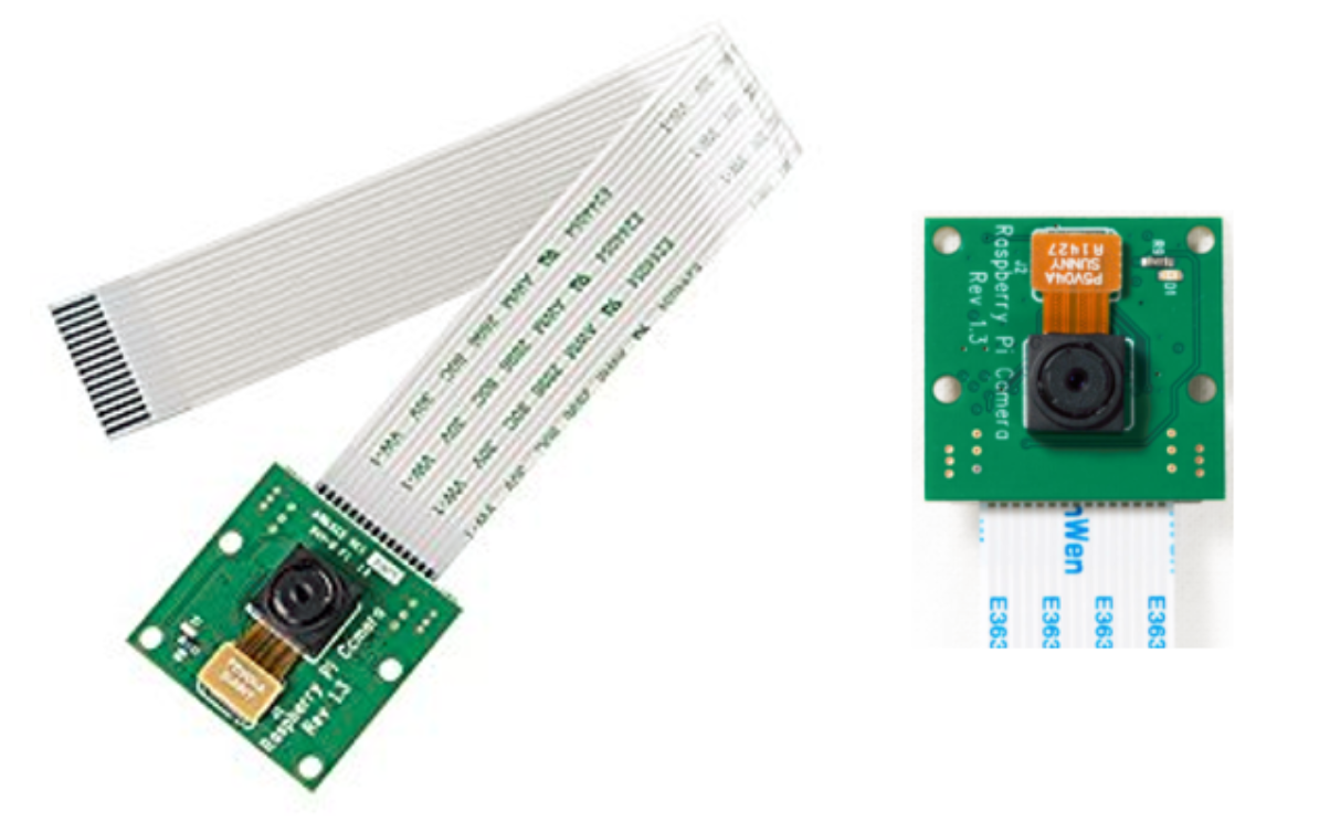
This camera module can be easily interfaced with the Raspberry Pi’s dedicated CSI camera port. This camera has a ribbon cable that attaches the camera to Pi. Refer to the official video by the Raspberry Pi foundation to install the camera on the Pi correctly. The following is the video link.
We have learned about each and every component required to build the security surveillance system except the Raspberry Pi itself, which is the heart of the system.
TL;DR
During our journey through this project, we discussed PIR sensors in detail. We have also learned how to use Raspberry Pi camera module and how to send email notification programmatically; finally we stitched together all the components to build a security surveillance system. Now, we can go out without worrying about the security of our home in our absence.
Reference
Modified and implemented from:
Rao, M 2018, Internet of Things with Raspberry Pi 3, Packt